
Showing posts with label Principles of Architecture. Show all posts
Showing posts with label Principles of Architecture. Show all posts
Monday, 10 November 2014
My logo
I haven't shown my logo to this blog yet, we were asked to design a logo for our projects. I worked on some designs which I wasn't particular happy with. With a help of a logo generator I was able to create this logo. MAD mean Michaels Architectural Design, I have created it in a way that makes it memorable, MAD it a quick reference to my works.
Thursday, 16 October 2014
Story of modern architecture

So as our building environment is located in EU, I have looked at various of books that could help me narrow down the architectural styles that are used in Europe, This book "The Story of Modern Architecture of the 20th Century" offers a lot of valuable information in regards to architecture around Europe and specific styles which have been used in some areas more than others. The book also presents a timeline which is very valuable.
Book offers wide range of historical buildings, architectural design styles, specific timeline and concurrent design principles, information regarding cultures. Well pretty much the progress of architecture and the build environment around the world over the last few centuries.
Tuesday, 14 October 2014
Quantity surveying of our bridge...
 So this is just a follow up of our first assignment, we are requested to carry out a quantity research of our structures. So even though our design may not have been the strongest of all, it could certainly take the lead in terms of the cost of materials. Seeing the other groups have almost all materials incorporated in their designs, our one only uses foam board. To calculate the estimate of material usage I disassembled our bridge and put have putted the pieces together so the make rectangles (easy to calculate the area and the using those calculations come up with the amount of foam board we have actually used.)
So I using the dimensions of these rectangles, I calculated their area and then added up all the sums together, which has given me 5940 cm^2. So this is the amount of foam board we have used, knowing that each foam board was 80 x 25 and there was three of them, I found our the area of one and then multiplied it by 3, giving me a sum of 6000 cm^2. So 60-5940=60, I have 60 cm^2 left. The whole bridge is made out of of almost three foam boards that we were given, nothing else that we were given was used, just the foam board.

So this is my first attempt on quantity surveying of the bridge, I hope that it's correct, or at least I am heading towards the right method.
Monday, 13 October 2014
Design proposal
By looking at the Clifton bridge and the use of suspension to secure the strength I came up with a design that is frankly quite simple. Even though it might not hold a lot of weigh it'd be fun to build it just to see how it will react to the load and whether it corrects some of the points we failed on. So this is me trying to recreate Clifton bridge with the materials we have, not entirely sure whether the feasible. This is basically me exploring different styles of technique, we already build an arch, perhaps suspension is the one. "A TEAM" have used suspension really intelligently, their structure held more weight than expected. From the looks of things the structure wouldn't twist due to the rope, till be using its own structure to counter weigh the live load and the foam beams support it.

Sunday, 12 October 2014
Clifton Suspension Bridge
Clifton suspension bridge spans across 412 meter gap, it's a construction which can link to our assignment, the bridge uses suspension as the name suggest, it spans across a long distance without any arch or any kind of support from the bottom.
The bridge suspension has two points of origin, one at each end. The tower like structure sends down the chains, down to the centre and then up to the other end. I could see how this design could come in handy if we were to redo the assignment, it's defiantly an option. Although with the use of materials we were given it'll be pretty difficult to make, the towers are made out of stone, our set of given materials doesn't consist of anything that heavy.

The bridge suspension has two points of origin, one at each end. The tower like structure sends down the chains, down to the centre and then up to the other end. I could see how this design could come in handy if we were to redo the assignment, it's defiantly an option. Although with the use of materials we were given it'll be pretty difficult to make, the towers are made out of stone, our set of given materials doesn't consist of anything that heavy.
Further Research
So I have committed to further research in terms of our assignment, "Introduction to architectural technology" by Pete Silver/ Will McLean have given me some insights to the science behind live and dead loads.
It's a really useful book as it covers a wide range of topics which are linked to our assignment. Perhaps given more time to plan the construction we could have incorporated some of the techniques included in this book. As our lecturer has said before, this is not a bridge we're building. With the materials we were given we could have incorporated some kind of suspension by the use of string, but most importantly change the arch.
The arch is what caused the failure, centre section was just so thick that it gave away, in a form of torsion or twist, we were focusing to make the building so stable that we didn't realise that the structure will counter itself. This very book touches on this particular subject, how to deal with Loads, live or dead and torsion.

If we were to have more time to carry out research we could have build a better structure, the chapter in this book covers this very topic, it more so introduces the readers to the torsion within structures and forms. Although not very detail, its a starting point which could have potentially lead into further research more in-depth. Bridges were our context but looking more in detail, this is something we would have aimed for.
It's a really useful book as it covers a wide range of topics which are linked to our assignment. Perhaps given more time to plan the construction we could have incorporated some of the techniques included in this book. As our lecturer has said before, this is not a bridge we're building. With the materials we were given we could have incorporated some kind of suspension by the use of string, but most importantly change the arch.

The arch is what caused the failure, centre section was just so thick that it gave away, in a form of torsion or twist, we were focusing to make the building so stable that we didn't realise that the structure will counter itself. This very book touches on this particular subject, how to deal with Loads, live or dead and torsion.
If we were to have more time to carry out research we could have build a better structure, the chapter in this book covers this very topic, it more so introduces the readers to the torsion within structures and forms. Although not very detail, its a starting point which could have potentially lead into further research more in-depth. Bridges were our context but looking more in detail, this is something we would have aimed for.
Friday, 10 October 2014
Bridges Bridges Bridges....
Thinking about our recent assignment I have researched few existing bridges, even though the assignment is not about bridges, its pretty much a structure that relates well to our specifications.
 Searching for images of bridges, as I wanted to find the context. There was a lot of links and images as bridges is a broad subject. Anyhow narrowing down my search I have come across this image. It shows different kind of bridges, I can visually reference some of the models made in class to some of those. These are interesting as some are easier to read and others leave me scratching head, what's good about this image is that the bridges are spanning across a gap, there is no middle arch to support the whole structure from the ground. I find these very interesting as maybe we should have incorporated further research before committing to designing, although we all did some research, it could have been done on a bigger scale. Knowing that the centre of our structure was the weakest point maybe looking into arches in greater detail could have helped us avoid this.
Searching for images of bridges, as I wanted to find the context. There was a lot of links and images as bridges is a broad subject. Anyhow narrowing down my search I have come across this image. It shows different kind of bridges, I can visually reference some of the models made in class to some of those. These are interesting as some are easier to read and others leave me scratching head, what's good about this image is that the bridges are spanning across a gap, there is no middle arch to support the whole structure from the ground. I find these very interesting as maybe we should have incorporated further research before committing to designing, although we all did some research, it could have been done on a bigger scale. Knowing that the centre of our structure was the weakest point maybe looking into arches in greater detail could have helped us avoid this.
Tuesday, 7 October 2014
Testing our structure to destruction
So as it happened today we have tested out structures to destruction, prior to the test me and few others have met and we all came up with a solution to extend the bridge as it was pretty short, our solution was based around the birds mouth idea that previously Doug and Sophie introduced. So we decided to draw out and cut out the four stands our structure will be supported by, those were positioned on the table but also on the side of it, Looking at the picture you can understand how it works (structure is upside down).
 So this is what the final element looked like, perhaps upside down its hard to see but below you can see the picture of Donnie setting it up prior to the test. The birds mouth lies onto the table taking some stress from the load but mostly extending the whole structure. Our structure managed to resist the weight of 1.9kg, although we estimated 2kg we were only 100 grams away. Its not bad and the structure only shown signs of failure on the joints for few seconds but our mechanism that was overlapping each part managed to work later on, what did give in was the middle part, where the bridge is at its thinnest point, the structure started to wobble and the it almost exactly in the centre. Overall I am pretty satisfied with the structure.

Thursday, 2 October 2014
Making the final structure...
So after some of the difficulties we have faced yesterday we decided to meet today and build the final version of our structure. Doug, Rhia and Sophie were able to tell us their ideas and suggestion through Facebook group last night as today they all in lectures. Diedonne and I were in task of building the final structure and applying the changes...
 So although this design was very solid and could resist a weight of the brick, it had its disadvantages too. Firstly we have used a lot more material than we were delegated, this is not good as it'll come up on our quantity surveying report and also its not fair to other groups. In essence we were able to build a strong structure however it will cost more than we had in our budget.
As we were building the final structure we have used Doug's guidance to cut out arches which are not as high, meaning we would save up some foam board and remain the same amount of strength. So to start of the whole build me and Diedonne have cut out six pieces from two foam boards, one foam board was cut out into two (centre section) and the second foam board was cut out into four (half arches at each end).
 So we began the work by measuring out the arches and cutting them out, to measure the arch we used a rope and a pencil, locating the centre line we were able to create the semi arches and full arch. once we had that figured out we have cut out the joints, we both decided that the joints will be cut out with very low tolerance, therefore we no longer were able to slide the joints together, instead we had to use great force to push them in, this itself provided a stronger joint, without the use of rope to stitch the parts together.
We decided that he joints provided a very effective solution for our problem with tension and weight resistance, under suggestion from Massood we incorporated this even further in our structure.
The support that will connect the two arched elements was going to slide upwards over the joints, it will also be connected by the same technique, low tolerance and force to push it together. so we had one of those supporting elements coming from the bottom up, to hold the joints, but we also decided to use another one coming from the opposite direction, coming down onto the joints. this created this system that was not going to allow the joints to come apart. for even stronger solution we added ones that will hold the two supporting elements together from the side.


Our finished structure was able to withstand the weight of a brick. It seemed like a superb solution, we were very economical on the use of material, only using two and a half boards, we used no other material. The bigger we are facing is the length, we have to spam the gap of 1.5m and our structure is only 1540mm long, gravity pulling the live load during could collapse the structure, not due to the weakness of it but due to the length. We still have got a lot of material left to play about with, our aim on Monday lunch is to extend the design and incorporate Sophie's initial idea of using the tables to take some stress from the structure.

As we were building the final structure we have used Doug's guidance to cut out arches which are not as high, meaning we would save up some foam board and remain the same amount of strength. So to start of the whole build me and Diedonne have cut out six pieces from two foam boards, one foam board was cut out into two (centre section) and the second foam board was cut out into four (half arches at each end).
We decided that he joints provided a very effective solution for our problem with tension and weight resistance, under suggestion from Massood we incorporated this even further in our structure.
The support that will connect the two arched elements was going to slide upwards over the joints, it will also be connected by the same technique, low tolerance and force to push it together. so we had one of those supporting elements coming from the bottom up, to hold the joints, but we also decided to use another one coming from the opposite direction, coming down onto the joints. this created this system that was not going to allow the joints to come apart. for even stronger solution we added ones that will hold the two supporting elements together from the side.
Our finished structure was able to withstand the weight of a brick. It seemed like a superb solution, we were very economical on the use of material, only using two and a half boards, we used no other material. The bigger we are facing is the length, we have to spam the gap of 1.5m and our structure is only 1540mm long, gravity pulling the live load during could collapse the structure, not due to the weakness of it but due to the length. We still have got a lot of material left to play about with, our aim on Monday lunch is to extend the design and incorporate Sophie's initial idea of using the tables to take some stress from the structure.
Wednesday, 1 October 2014
Making the element...
So this morning we gathered together at 10am to turn our initial ideas into reality. We have decided to keep Doug's idea as our primary one and mine as an alternative idea. It was quite an experience as there was a lot of things I have learnt about the project, modelling and myself throughout the day.
 Our materials, although we were not allowed to add any additional materials, we had a green light to create prototypes of both designs by reusing some old foam board.
We divided our groups, myself and Dieudonne have worked on my idea, Doug and Pedro would work on Doug's idea whilst Rhia and Sophie were taking pictures and recording the events that took place throughout the build, they have also helped in each design by suggesting new ideas in regards to technique and application of materials into the construction.
Both Dieudonne and I began to work on my idea, the I beam supported span. My aim was to build a deck that would be 150 mm wide and 1600 mm long, underneath it would be a set of foam boards positioned vertically, that way the foam tensions resistance is greater than if it would be positioned flat, this would just make it bend at its weakest spots. The diagram on the left shows how the load will affect the material and the tensions within it.
 This is the kind of technique I tried to apply in my initial idea. Both dieudonne and began to create the prototype under the supervision of Sophie and Rhia.
The main focus of mine and Dieudonnes work was to attach the pieces to the bottom of the deck, We used scissors in to make holes through which we put through the rope in order to make a system that will hold the deck and supporting foam board together like so...

What the system consists of is mainly a rope that will go through the two pieces and create a "T" like structure. we would have double the middle section as the centre of the element appeared the most vulnerable to me. The deck would be 150mm wide as it allow us to make two stripes from each board 50mm x 800mm to be used as support. We positioned two boards next to each other creating a span of 1600, the other piece of foam would be positioned on top of the two,
 On the left is our prototype being tested to until it shows signs of failure. We now have made the centre really strong but the ends of the centre support now became the weak points where the construction seemed to fail. Christian, Rhia and Sophie all worked really hard to help us generate the a solid support and get rid of the vulnerable points. We have come up with two ideas to improve the build.
Christians idea of making the construction more stable.
Our new team member who we met today has suggested that we lengthen the centre support as it appeared to be very strong by attaching the four panels to the ends of the centre support.

So once we made the connection right away we have increased the strength of our bridge, the ends of each support lines attach to the centre support whereas the ends that are positioned on the table are separated, this has given us a lot more stability.
Sophie's suggestion of making the bridge stronger
She has suggested that we would keep the element turned upside down in order to create a stronger the structure. Reason being is that the support panels are divided into three sections, when they are on the bottom of the design the dead weigh of the platform separates the panels away from each other, whereas when they are positioned upside down the panels actually press into each other, giving us just a little more strength.
We have decided to keep the spam upside down, one concern that Rhia pointed out was that the platform on which the weigh will be positioned for testing needs a solid support as it will be impossible to balance the platform on thin part of foam board in the centre, as you can see on the picture above.
-------------------------------------------------------------------------------------------------------------------------
Doug's Idea of the element spanning the gap.
Just as we finished making the prototype we have gathered together to discuss the pros's and con's of the prototype of our alternative idea, alternative for a reason because that's when I saw Doug's prototype, it was a great idea, right away it showed me the standard of knowledge and application second year student have on this course. Doug's idea was pretty much a master piece...

Shortly after seeing this design we all dropped our stuff and tried to help building this structure, each taking various roles like piercing and making knots to hold the joints, cutting the foam, brainstorming ideas and also sharing our thoughts and implementing it into the design.
 As each joint had a knot on it, this would give additional support to the foam to prevent it from falling apart from each other. There would be two of those on each joint, Eight in total.
It was difficult to make the knots really tight as the rope was very close to the foam and tying it was pretty hard as the rope kept stretching out, making the joints very loose.
 almost finished prototype prior to the test, the construction seemed very neat, We have used bottle of watter for a quick test before we put any heavy load on it, the test went well the construction managed to hold the weight. Although when we positioned a brick onto the platform, the structure started leaning on one side, it was a sign of failure. We have decided to follow a similar principle that was used on my idea after Christian suggested that we keep the centre as it is but just spread the ends a little. This was on point as the bridge later on held the brick for some time before Diuedonne had removed it.


So our prototype succeed, Doug delegated the creation of the actual model to me and Diuedonne, shortly after the group have dismissed me and Diuedonne realised that a lot more material was incorporated into the structure than we had available. This meant that we can in fact build a very strong element which spans the gap although it would need a lot more foam board. Me and Diuedonne tried to come up with some alternative ideas but we did five and a half of non stop work on my idea and we assisted Doug, after such time we were both pretty much exhausted, the mind wasn't working and the ideas weren't flowing. We have decided to meed on Thursday morning and create the element, second years have told us they would help during their breaks which shows a really good commitment to the project from their side, dedicating their free time to help us rebuilding the structure from scrap.
We divided our groups, myself and Dieudonne have worked on my idea, Doug and Pedro would work on Doug's idea whilst Rhia and Sophie were taking pictures and recording the events that took place throughout the build, they have also helped in each design by suggesting new ideas in regards to technique and application of materials into the construction.
Both Dieudonne and I began to work on my idea, the I beam supported span. My aim was to build a deck that would be 150 mm wide and 1600 mm long, underneath it would be a set of foam boards positioned vertically, that way the foam tensions resistance is greater than if it would be positioned flat, this would just make it bend at its weakest spots. The diagram on the left shows how the load will affect the material and the tensions within it.
This is the kind of technique I tried to apply in my initial idea. Both dieudonne and began to create the prototype under the supervision of Sophie and Rhia.The main focus of mine and Dieudonnes work was to attach the pieces to the bottom of the deck, We used scissors in to make holes through which we put through the rope in order to make a system that will hold the deck and supporting foam board together like so...
What the system consists of is mainly a rope that will go through the two pieces and create a "T" like structure. we would have double the middle section as the centre of the element appeared the most vulnerable to me. The deck would be 150mm wide as it allow us to make two stripes from each board 50mm x 800mm to be used as support. We positioned two boards next to each other creating a span of 1600, the other piece of foam would be positioned on top of the two,
Christians idea of making the construction more stable.
Our new team member who we met today has suggested that we lengthen the centre support as it appeared to be very strong by attaching the four panels to the ends of the centre support.
So once we made the connection right away we have increased the strength of our bridge, the ends of each support lines attach to the centre support whereas the ends that are positioned on the table are separated, this has given us a lot more stability.
Sophie's suggestion of making the bridge stronger
She has suggested that we would keep the element turned upside down in order to create a stronger the structure. Reason being is that the support panels are divided into three sections, when they are on the bottom of the design the dead weigh of the platform separates the panels away from each other, whereas when they are positioned upside down the panels actually press into each other, giving us just a little more strength.
We have decided to keep the spam upside down, one concern that Rhia pointed out was that the platform on which the weigh will be positioned for testing needs a solid support as it will be impossible to balance the platform on thin part of foam board in the centre, as you can see on the picture above.
-------------------------------------------------------------------------------------------------------------------------
Doug's Idea of the element spanning the gap.
Just as we finished making the prototype we have gathered together to discuss the pros's and con's of the prototype of our alternative idea, alternative for a reason because that's when I saw Doug's prototype, it was a great idea, right away it showed me the standard of knowledge and application second year student have on this course. Doug's idea was pretty much a master piece...
Shortly after seeing this design we all dropped our stuff and tried to help building this structure, each taking various roles like piercing and making knots to hold the joints, cutting the foam, brainstorming ideas and also sharing our thoughts and implementing it into the design.
It was difficult to make the knots really tight as the rope was very close to the foam and tying it was pretty hard as the rope kept stretching out, making the joints very loose.
almost finished prototype prior to the test, the construction seemed very neat, We have used bottle of watter for a quick test before we put any heavy load on it, the test went well the construction managed to hold the weight. Although when we positioned a brick onto the platform, the structure started leaning on one side, it was a sign of failure. We have decided to follow a similar principle that was used on my idea after Christian suggested that we keep the centre as it is but just spread the ends a little. This was on point as the bridge later on held the brick for some time before Diuedonne had removed it.My very first assignment as a student of architectural technology
Yesterday we've been introduced to our module and assignments, the very first assignments is named 'Span the gap'. Prior to the introduction we were introduced to second year students who have been delegated to guide us through this assignment.
 On the left you see Dieudonnes innitial idea in regards to the structure of the element. The main concern we had with the idea was the height of the brace as its the location where the weight would be placed for testing purposes. Sophie suggested that we make the cuts on the ends of the construction which will help the design to spread its own load as well as any other (loads of the weights) the whole construction would be in a lot of stress during the testing. There was also an issue of how the two separate pieces will be attached and how wide they have to be spread out in order to span the gap.
 Almost right away Doug had an idea in his head, one that was very technical as well as functional. He had researched various bridges and the technique which was applied in order to build them. His idea was based around the arches. The initial design had a very promising touch to it, we all knew right away that this was going to be the first idea we would try out the next day the moment we say his technical drawings. When I saw the drawings at first I wasn't convinced that the design would be able to take a lot of stress as I was aware that the gap would stretch the design, it would be impossible to make the construction that high and long with given materials. Another thing that I have noticed was that the arches drop down a little, we were given specific measurements which state how low we can go and how much into the tables we can put our construction. It was hard to see the idea in reality as the drawings were not to scale, but it was a promising start and we were going to discuss it in the morning right away.

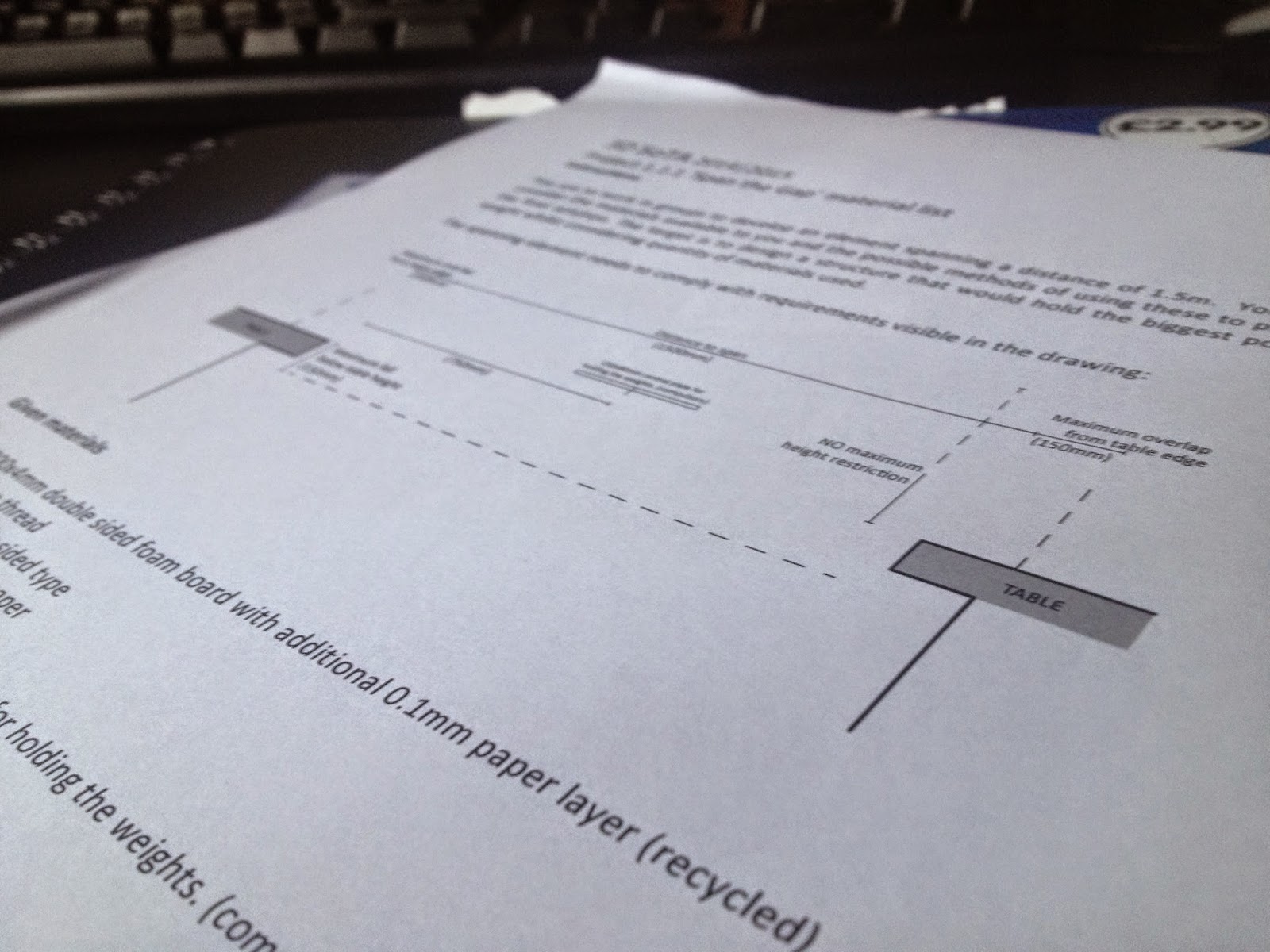
My group consists of myself, Pedro and Dieudonne as the first year students guided by Rhia, Doug and Sophie who are the second year students. Right after we formed out team we were introduced to the brief. Our aim is to build an element spanning the distance of 1.5m, the challenge however came in a form of the materials available, we were given material which must be used to build the construction, right away we figured that it will be pretty difficult to make the construction as the brief states clearly that no other materials or adhesives can be incorporated into the project.
Right after getting to know the assignment we decided to do a brain storm of our individual ideas which we then reflected on as a group. My initial idea was to create a platform which would have been supported by the foam board which was positioned vertically underneath the deck. My group have considered my design as strong however the was an issue associated to how I was going attach the pieces of foam board. So right away after yesterdays group chat I knew the strengths and weaknesses of my idea. Main pro of my design was the fact that I positioned the supporting foam board pieces vertically so that it has higher resistance to tension and is a lot less flexible. Doug and Dieudonne have also introduced our group to their approach, Doug's design was concerned with arches and foam board engineering whereas Dieudonnes idea was to create an A frame to spread the dead load of the construction onto the tables.
This is my design that I've tried to make up to scale although some elements are a little over exaggerated in terms of their scale, just so I can display the details to others. My influence came from the book "Introduction to architectural technology" its first few pages explained how different techniques can be applied in order to achieve increased tensions resistance. I pretty much imagined the bottom elements to be like I beams, supporting the construction of buildings. It was my very first thought although I was being ambitious, the main problem was with connecting the pieces of foam.
We have all been added to a Facebook group chat through which we talked about our project, it was a good way to present our ideas before we came in the next day to build the element.
Subscribe to:
Posts (Atom)